2000 Honda Civic Main Relay Wiring Diagram
A lot of people, like me, are not able to locate the PGM-FI main relay, which is also called the Fuel Pump Relay or just Main Relay.
So here is the Mystery relay
I am having some trouble with random starting issues, where the car would crank, but not start. I get random codes each time, which makes it difficult to troubleshot and point out the exact problem. So in one of the forums someone asked me to check the fuel pump relay, and remove the board and inspect it for any cracked solder. I had no idea what he was referring to (not blaming him for that, just lack of my knowledge), until I did my research and found it out.
So what is this PGM-FI? It's a short form, and a fancy name given by Honda, for Programmed Fuel Injection. Also commonly known as Fuel Pump Relay or Main relay.
This is very common to most of the Honda / Acura and even the location might be in the same place. But please check your manual to verify.
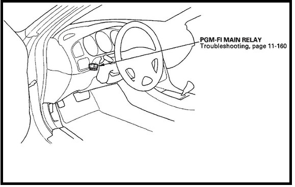
If you have the service manual, it shows the location of the PGM-FI (see photo below), but looking at that there is no way to identify it, where exactly it is and which one it is. If you open the dashboard lower cover (instructions given below) which is below the steering wheel, there a lot of wiring harnesses there, and it is not very easy to locate the PGM-FI main relay.
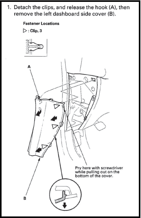
First remove the left dashboard side cover, which is the driver side fuse box cover.
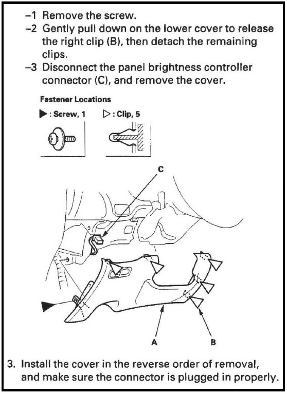
Then remove the one screw and gently pull down to release the 5 clips, marked below.
Please be careful of the wiring harness for the instrument light dimmer, which is connected to this cover
These are the 5 clips.
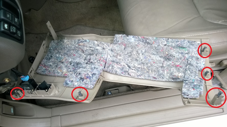
You can either remove the socket for the instrument light dimmer, or leave it connected and carefully lay it to the side.
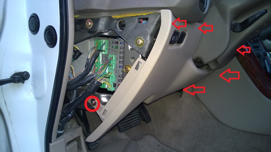
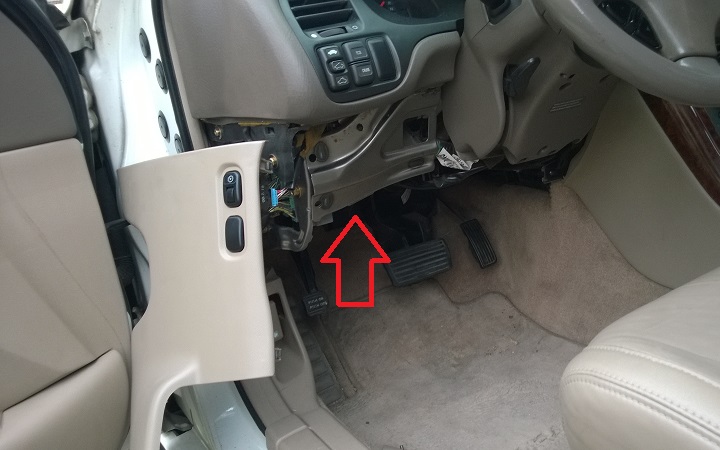
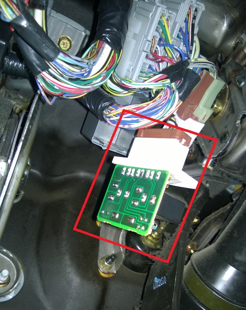
Now this is where the PGM-FI main relay is located. (marked with the arrow)
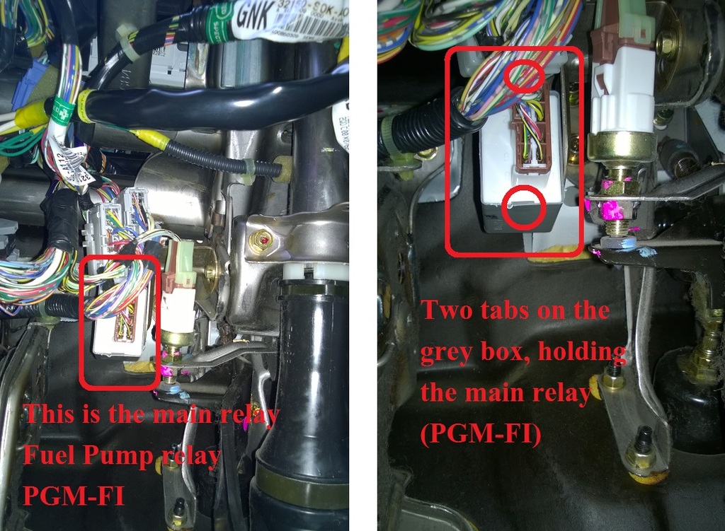
Once you get under the steering column; you will see a grey box, with a brown socket connected to a white face plate, which is the PGM-FI.
You can either remove the brown socket, and then remove the PGM-FI main relay or remove them together, which is easier, as you have something to hold onto and pull.
The white face plate of the PGM-FI is held inside the grey box with the help of two tabs, one on top and one on the bottom. In the photo below, you can see the one on the bottom, circled red. There is similar one on the top.
Here is the lock for the brown connector and the grey box with the 2 tabs which hold the PGM-FI in place.
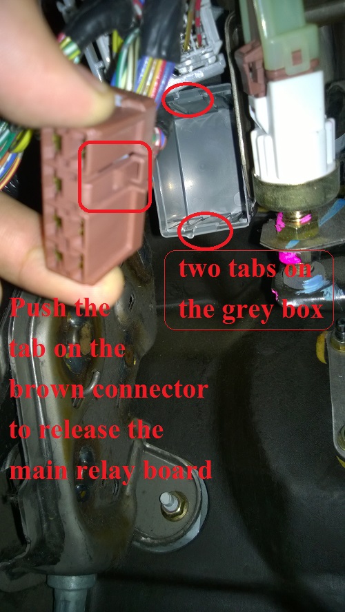
You can use a tiny flat screw driver or something, to pry the PGM-FI out of the grey box, which is a bit tricky, as there is not enough space and there is another big grey wiring harness right next to it. Don't pull very hard, as there is not enough slack for the wires. Once pulled out you will see the bare naked PGM-FI circuit board. Now you can disconnect the brown harness from the PGM-FI and take it inside for inspection.
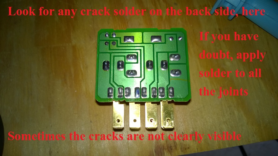
This is where you need to check for cracked solder on all the solder points. The white face plate will slide out of the contacts, and you can keep it aside until you ready to put it back. Remember it is not very easy to see the cracks, unless you have a microscope. I used a small magnifying glass to look at each of the solder joints for any crack or damage. I did not see any crack or damage, but I read somewhere that it would not hurt to add some solder to each joint, which will re-melt the old solder and bind it again, in case there was an invisible crack.
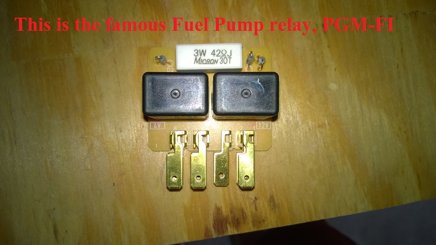
Here is the other side of the PGM-FI, which has 2 relays, a resistor of some kind, and a few diodes. (I'm not an electronic guy). Just check if everything is in place and nothing is broken.
To put it back, it's the same reverse order. But again I prefer to connect the brown wire harness to the PGM-FI and then slide them together into the grey box. Listen for the click once the white face plate of the PGM-FI is locked in place.
I hope this will be useful for someone like me, who was trying to search where is this mystery PGM-FI.
Cheers.
Source: https://acurazine.com/forums/2g-tl-problems-fixes-117/diy-locate-pgm-fi-fuel-pump-relay-main-relay-931252/
Posted by: fredricagrot1985esp.blogspot.com

Posting Komentar untuk "2000 Honda Civic Main Relay Wiring Diagram"